
Custom 3D Scanned and 3D Printed Lights for our Honda Beat Kei Car
The Honda Beat is still kicking around at our shop and we’re making modifications to it little by little. It’s been a fun car that requires a lot of labor and love. Recently we were able to get a 3D scanner and I knew the perfect project to break it in.

Custom LED tail lights on a Honda Beat kei car.
Earlier this year, I modified the taillights with a new acrylic lens and LEDs. That video blew up on Youtube and TikTok (kind of) and we received a lot of comments. Most comments were overwhelmingly positive and encouraging and some were not, but some were straight up mean. Those naysayers generally had qualms about the reverse light being red. To be fair, that was admittedly a feature that I did not initially think about.
Anyway, we were able to remedy that situation using the 3D scanner and satisfy all of the safety officers by making new reverse lights.
We took the steps below to develop a successful prototype. You can watch the video on Youtube using the link to the right >
If you prefer reading, we try to add more details about our thought process here so... happy reading!
Here are the links to the products we used:
Creality CR-Lizard 3D Scanner: https://amzn.to/3PUrqWL
3M Double Sided Tape: https://amzn.to/3FT5zKD
Ender 3 3D Printer: https://amzn.to/3vdW6bQ
LED Lights: https://amzn.to/3VkKHS9
ASA 3D Printing Filament: https://amzn.to/3VqACTP
Waterproof wire connectors: https://amzn.to/3jswPbs
Foot Powder Spray: https://amzn.to/3WovQYl
Jigsaw blade: https://amzn.to/3FW7e1R
Deburring tool: https://amzn.to/3C0dtRc

(Left) OEM tail light for the Honda Beat next to the modified tail light (Right).
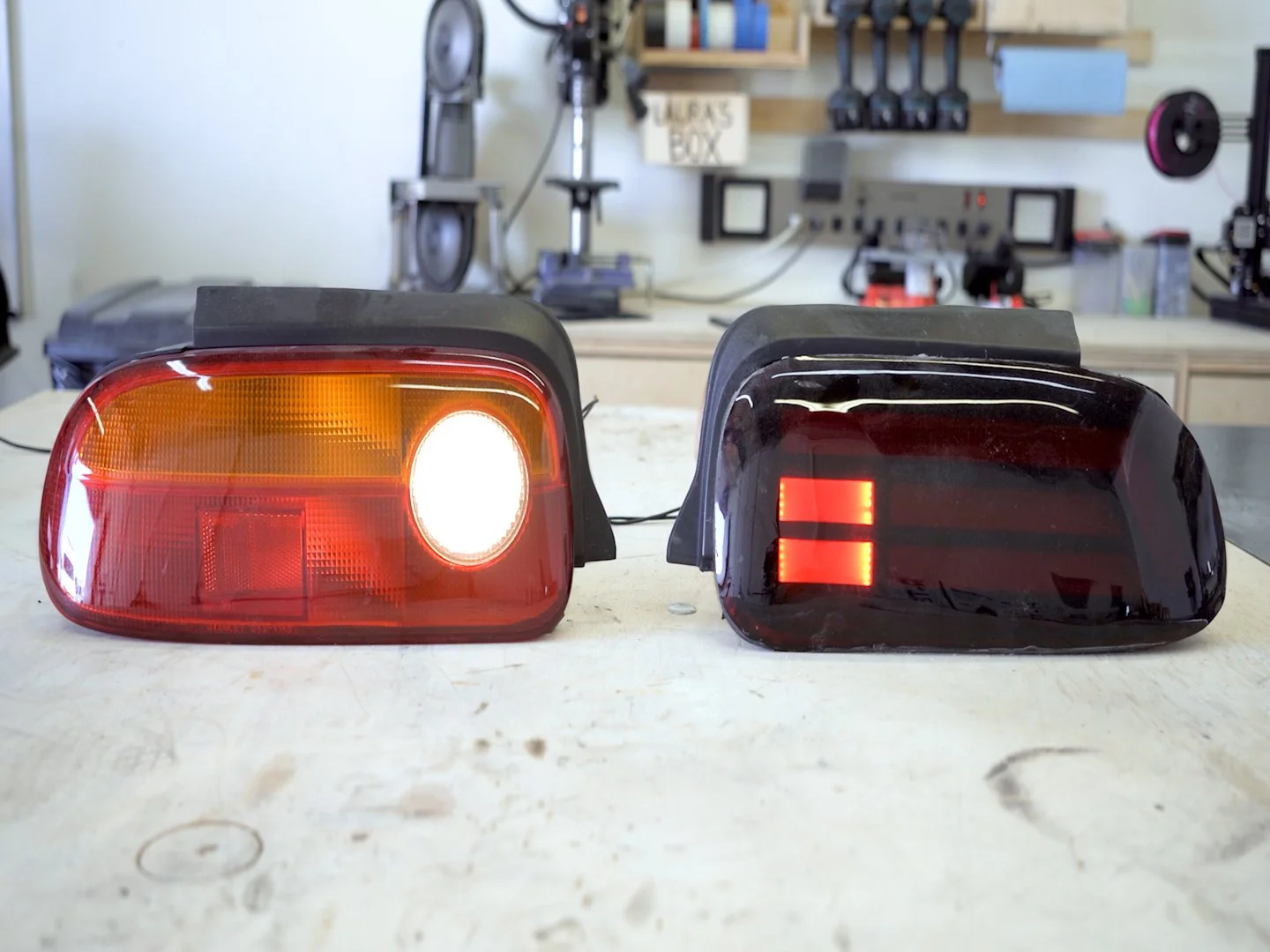
(Left) OEM tail light reverse light for the Honda Beat next to the modified tail light reverse light (Right).
For context, the left tail light above is the OEM light for the Honda Beat. The right tail light is the updated, LED version I made a few weeks ago. (Watch the video here.) You can see that the new reverse light is the section that looks like an equals sign (=).

Creality kindly sent us their CR-Lizard 3D scanner to help us bring this project to life. It’s an entry level 3D scanner and overall pretty straightforward to use. The kit comes with a turntable, but you can also use it in handheld mode. It does not have great precision when it comes to scanning large, flat objects like bumpers and fenders off the bat, but with a few work arounds and patience, it produces really good 3D models.


Since this particular scanner doesn’t use tracking dots, we have to prep the surfaces we want to scan. We’re only focusing on the left side of the car since the model can be mirrored to the other side.
First we used foot powder spray to dull the shiny surfaces and wait for it to dry. In the meantime, I covered the taillight with painter’s tape as well because the spray alone didn’t remove all the reflections.
Then we cut thin strips of masking tape and applied it in random patterns all around the bumper surface.
As mentioned before, the CR-Lizard Scanner doesn’t use tracking dots, but instead uses just light. The software then determines the position of the points on the current frame relative to the previous frame. So, if the areas are too similar, meaning there is no variation in the surface, the software will stack each of the frames on top of each other making a jumbled mess.
The masking tape helps create differences in geometry for the scanner to recognize and then compare to the previous frame. Then it can place the points correctly in space for each frame.
Pro Tip: When scanning body panels and bumpers, make sure to use “Texture” mode when scanning and have minimal lights around to reduce glare. This was the key for a successful scan.

Once the scanning was complete, I cleaned up the point cloud by removing the floating bits and unnecessary components. The model takes up a lot of memory, so anything to minimize the file size is helpful.

Once I was happy with the point cloud, I processed the model and uploaded the .OBJ file into Fusion 360.
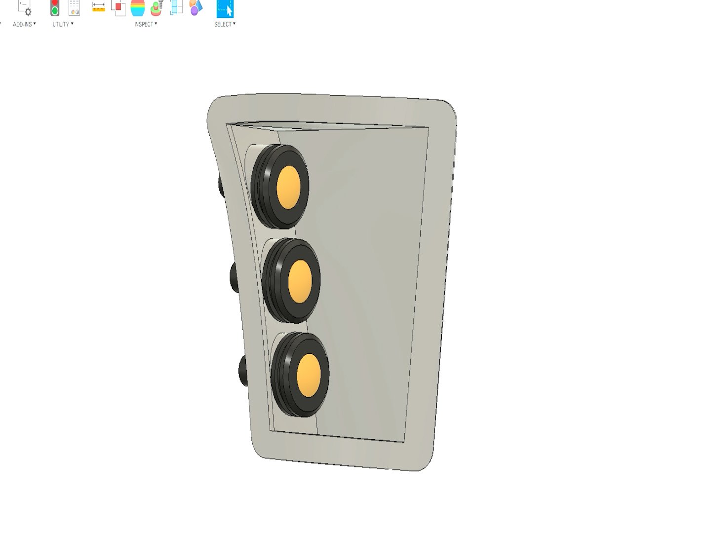
To start the model, I used the form tool and made a shape that snapped to the bumper mesh file. Then I built upon that frame and added the other components to the bezel.
You can download the FREE STL files to make your own modified lights by clicking the link below.


With the 3D model completed, I sent it over to our 3D Printer. We used ASA filament because, like ABS, it’s heat resistant, weather proof, and all that important stuff. I didn’t go the extra step to smooth out the layer lines, prime and paint it because this is a version 1. More upgrades to the bumper may (or may not) take place, so I wanted to keep the prototype look for now.
Next we mounted the LED pod lights to the bezel, shortened the wire harness, and added a weatherproof connector.
Now that we have the reverse light bezel completed, I taped up the area of the bumper that was to be cut.
FYI, I also 3D printed a template that is just the outer ring of the bezel so I can position it and mark the area that needs to be cut.


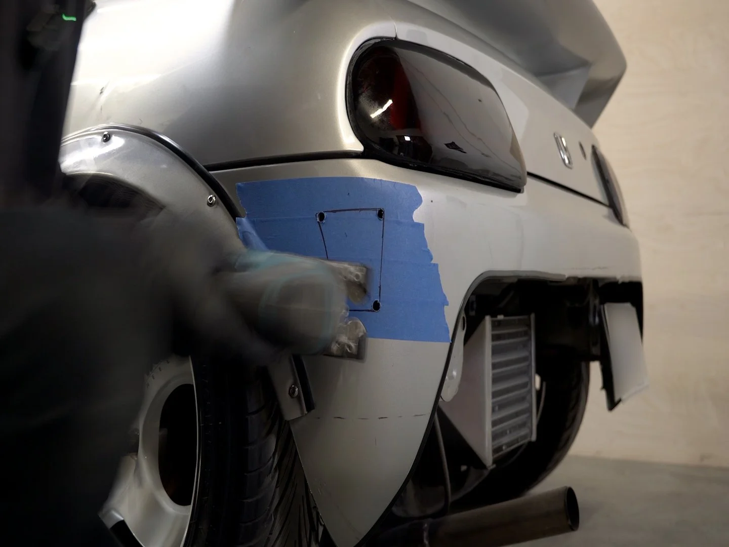

Then I got to cutting. I used a jigsaw with a thin kerf blade and it cut through the ABS bumper like butter.
I repeated all the steps on the other side of the bumper and wired everything in. The wiring is very straight forward. Basically, I combined all the positive wires and all the ground wires from the LED pod lights and wired them into a 2 pin connector. Then, I made a receiving 2 pin connect with a positive and negative pigtail that taps into the reverse light wires on the respective tail light harness.
Have any questions? Find us on Instagram and DM us or email us at info@imeemade.com.
The new 3D printed bezels are held in with 3M double sided tape


We think the reverse lights came out so good! Plus, they’re super bright so there’s no way anyone can miss us when backing up. Sometimes it’s a good thing to read comments and take suggestion because it turns into a pretty great project.
Thanks for following along!